- Company: Chris-Hill Construction Company
- Industry: General Building
- Location: Memphis, Tennessee
- Project Website
The Great American Pyramid, as it was once called when first constructed in 1991, was built as a basketball arena and exhibit space by the city of Memphis in order to attract an NBA franchise. (see photo Pyramid at Night) Ironically, when Memphis recruited the Vancouver Grizzlies in the Mid-2000’s, one of the demands of the Grizzlies ownership was that Memphis would need to build a brand new arena in order for the Grizzlies to move. The building of the new FedEx Forum, current home of the Memphis Grizzlies NBA team, meant that the Pyramid would become obsolete unless it could find a buyer. Bass Pro Shops, after a long period of due diligence, agreed to purchase the Pyramid, with conditions. The Pyramid was constructed prior to IBC 2007 seismic codes which meant that the City would have to retrofit the entire structure to accommodate a new retail facility. This POY submission by Chris-Hill Construction Company, Pyramid Package #2, is the below ground seismic construction package that ensured the Pyramid would not move laterally during an earthquake or fail due to instability of the adjacent Mississippi River bank.(see attached Pyramid Rendering)
The following are details describing WHY this project deserves to become an I Build America Project winner:
What impact does this project have on America?
This project provided 20 jobs for construction trades for 6 months. This may not seem like much but it is a big deal to each worker. Providing jobs to our 70 employees is the main reason we do construction. Yes it can be satisfying, yes it can be difficult but the greatest satisfaction is putting good men and women to work every day and paying these folks every week (via HeavyJob/ACH direct deposit, we might add).Keeping people employed with good paying, mind stimulating, sweat producing jobs is the greatest asset to American freedom imaginable, and we have been privileged enough to do this for the last 51 years.
What interesting obstacles or unusual circumstances did you overcome to complete the project?
Once our design settled on the combi-wall, shear fin arrangement we had to determine what type of piling equipment would be best for installation. (See Drawings –Blowup of Shear Fins-Plan View) Each shear fin is comprised of a 14×73 H-Pile connected to a pair of AZ19-700 connected to a middle HP14x73 connected to another AZ19-700 connected to a final HP14x73. H-Piles were fitted with continuous C9 female interlocks.(see Section View C9/E22 Connectors) The outside H-Piles had one continuously welded C9 whereas the middle H-Pile had a C9 on each side. C9 interlocks were welded to 70’ long H-Piles in Skyline Steel’s fabrication shop in Blytheville, AR, across the street from the Nucor Steel Mill. AZ19-700 sheeting was rolled in Belgium, shipped to Savannah and trucked to Memphis. Typically, C9 connectors are welded to
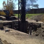
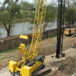
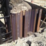
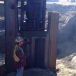
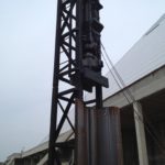
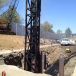
two sides of an H-Pile when fabricating combination walls. Welding to opposite flanges of a 70’ long H-Pile somewhat equalizes thermal bending stresses imparted due to continuous welding. All outside H-Piles had only one E22 connector continuously welded to one side which meant the piles bowed 8” to 12” after welding. The piles looked like 70’ long, steel bananas. Fortunately, Skyline had a custom made press built specifically for these types of problems. 2 to 3 cycles through the press dropped tolerances down to 1” to 2” of bow. Most piles also developed axial twist due to the heat related eccentricities developed during welding which was simply a problem we had to overcome during driving. Initially, our team agonized over the type of template we would construct to keep the combi-walls from racking and insure plumbness. Fortunately each shear fin panel was only 13’ long which meant that if the pieces did begin to rack out of plumb, the problem was not cumulative. One cannot generate too much tilting in a 13’ long run of wall. Thus, no template was used. Additionally, our designer determined that it was not necessary to reinforce the top 10’ of the soil profile. We decided to save the top 10’ of steel and drive pile tops to -10’ for several reasons. First, storm drainage, 6” water lines and electrical lines were all less than 10’ deep. Any interference we discovered in digging to -10’ deep could either be relocated quickly or our shear fins could be shifted to miss them. Second, future utilities would also be free from conflicts with shear fins. Our most difficult and time consuming activity was capping and driving alternating pile types, sheets to H-Piles and back to sheets. Our standard H-Pile helmet (cap) easily fit atop HP 14×73’s in both X and Y axes. (see photo Capping H-Pile) However, driving the sheet piling with an impact hammer was not as easy. We found a pile cap manufactured by ICE called a DCS-5. It is made to fit the deeper sheets with large H (height) dimensions (see Drawing of AZ-19-700). We found that the DCS-5 would cap a pair of AZ19’s with only ~3” of steel hanging outside both sides of the helmet. (see photo DCS-5 Capping Sheet Pair) The cap fit inside 32” leads and we chose an ICE I-30 diesel hammer to drive all the piles. Impacting was the way to go, especially since the 32” leads could be rotated to drive pairs of sheets. Unfortunately, we could not drive singles due to adjacent piles hitting the leads or hammer. This did mean that we would need a large amount of energy to mobilize a fairly large pair of sheets, avoiding fatigue of the pile tops. Our initial attempts to vibrate piles refused at about 30’ of penetration. Our second attempt to drive piles with the I-30 proved successful, but slow. We had to lead with the sheet pairs and follow with the H-Pile ‘guides’. Otherwise, the hammer could not cap the H-piles due to adjacent sheeting conflicts. Clutching or hitchhiking of the sheet-to-H-pile-connection was a major issue that caused delays. Welding interlocks only lasted around 15 minutes of driving. Pile tops eventually rolled and had to be torched off. However, fuel setting #1, although slow to drive, proved to be the optimum hammer setting. It was the lowest energy delivered but minimized the amount of fatigue to the pile tops. (see Photo Finished Shear Fin)
Unique application of piles or design considerations:
Foundations and walls built to seismic standards utilizing compression, tension or lateral elements are not uncommon applications for sheet piles and H-Piles. Rarely are driven steel piling used to improve weak soils during a lateral spreading seismic event. At the Pyramid, the project requirements were quite simple-keep the western part of the pyramid from moving more than 1” during a magnitude 6.5 earthquake. Our team knew the competition would bid deep soil mixing, jet grouting, slurry walls, augercast piles or a combination of these deep drilling methods. Our challenge was to create a better construction method, use superior materials and foremost become the lowest and best bid when compared to the drillers. Our team studied concentric sheet pile cells, parallel sheet pile walls tied together, mass fields of driven pipe piles and several other options. All of these options basically attempted to overpower the tremendous inertial loads imparted during an earthquake. The initial depths of repair suggested by the owner were walls 130 ft below grade, 600 lineal feet in length and 30’ thick. (see photo Concept Article in News) Our design effectively confined the soils, slowing the spreading of the loosest layer (30-60 deep) by inserting isolated combi-walls (shear fins) parallel to the direction of spreading. Lateral spacing between the individual fins range from 15’ to 20’ depending upon the stability of the soil layers. In essence, once the seismic event begins, loose soils increase in pore pressure as loads increase. Shear fins react to confine and strengthen a 3-dimentional zone of soils, creating steel ‘cells’ that act as an integrated unit slowing or even preventing soils from spreading or moving laterally. This unique application of steel piles is novel, sophisticated in its design and deserves a hard look from the academic community on its future use across the world. As you can probably tell from our excitement in having the opportunity to present this project, we may be onto something here. (see Plan and Profile of Shear Fins)
Cost saving measures such as value engineering or innovative project management:
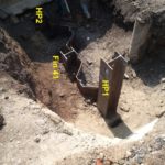
Running the entire length of this project, on a North/South alignment, was a 72” diameter RCP which drains a 4 square mile area and flows into the Mississippi River. During high water, this storm sewer has to be re-lifted into the flooded Mississippi to avoid flooding the Pyramid. Critical to this project was the maintenance of this storm drain. All other bidders who bid drilled soils techniques were forced to include removal, standby pumping and replacement of this 15’ deep storm drain. Our driven pile solution was flexible enough to narrowly miss any conflict with the drain (see photo Fin 41 Drain pipe). This one advantage resulted in our bid of $7.2mm being half the price of other bidders at $13.2mm and $13.9mm. All of you can imagine the ‘Woos!’ in the room when results were read out loud. I hope other contractors can sympathize with me when I had to explain to my surety bonding company why we bid half-price!
Design changes from other deep foundation or earth retention systems to driven piles:
When the City of Memphis agreed to upgrade the Pyramid to include the newest Seismic standards, they opted for a design-build delivery method mostly because they did not have any good ideas how to fix the problem. The City consulted with a large soil mixing contractor and had basically settled on negotiating the project with Hayward Baker. Fortunately, the City decided to allow other ideas to be submitted and opened up the project to other contractors. Since Hayward Baker had provided so much information to the City Engineers, the project manual was basically written around deep soil mixing including design criteria, methods of payment, limits of construction and depth of construction. Since very few companies perform deep soil mixing and only one of these 5was bidding this project, it was in our best interest to design a quick and simple solution. The biggest concern was the depth of the design and the methods utilized to drive piles to what started as 120’ deep. Once our designer ran time history studies using finite element seismic analysis techniques and determined that the weak soils were not necessarily 120’ deep but somewhat shallower, only then did driven piles become the most feasible alternative. We knew we could drive piles 80’ deep (10’ cut + 70’ piles depth) even if we were forced to pre-drilling 80’ deep holes. Keep in mind that this project was constructed 50’ from the base of the pyramid on one side and 25’ from a Corps of Engineers Mississippi Flood wall on the other side. (see photo Driving Pair AZ 19-700’s) The Pyramid was constructed on deep foundations but only part of the floodwall was on piles with a section constructed on spread footings. To make matters worse, we discovered after the bid that this part of the wall had settled during the construction of the Pyramid back in 1991. And here we were considering impacting piles next to both structures! Our solution was an extensive monitoring program involving both hard surveys and vibration monitoring of the structures. (see photo Vibration Monitor) I would have given the advantage to drilled methodology when vibration is considered critical, but with a well implemented monitoring plan and extensive pre-construction vibration monitoring, potential problems were greatly reduced, an indeed proved to be eliminated. The flexibility of a driven pile solution coupled with the reduced footprint required to achieve acceptable results proved driven piles as the superior solution to this problem.
Management or mitigation of environmental considerations:
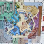
The top 12’ to 15’ of earth that we removed in order to countersink combi-wall piles was considered mildly contaminated and not allowed to be hauled off site (see photo Backfill Operations).These dirty soils contained sawdust, wood-ash, glass and solid trash dating from the early 1900’s. Fortunately, time had effectively digested most organics from the soils and with the help of the geotechnical testing firm, we were allowed to compact allof the contaminated material back into the excavated holes. (see Typical Daily Report) This backfill material, compacted to 95% standard proctor density, shrank significantly from its in-situ condition, leaving us 3’ extra of import dirt to finish the site to grade. Re-cycling dirty dirt insured that no outside landfills had to deal with our site’s environmental management problem. Additionally, about 10,000 lbs of steel cut-offs and 50 CY of concrete demolition were hauled to recycling facilities to mitigate the overall carbon footprint. Further, Chris-Hill’s use of the driven steel design allowed for the 72” storm drain to remain functional throughout the project. All other proposers planned on removing the massive storm drain and bypass pumping millions of gallons of rainwater with open air diesel bypass pumps for each rain event during the duration of the contract. Again, the implementation of this successful design element proved the most considerate of all designs for the environment. (see Bass Pro Floor Plan)
What dangers and risks did you encounter, and describe any extraordinary methods used to keep workers safe?
The City Engineers determined that the West side of the Pyramid Structure could move west due to seismic lateral spread and potentially fail due to slope instability of the east bank of the Mississippi River during an earthquake, causing extensive damage to the augercast foundations, poured in place substructure and metal truss superstructure. The City issued a call for design/build proposals to all interested bidders with no restrictions as to construction methodology in solving the seismic problem. Simply put, the owner required no more than 1” of lateral movement during a magnitude 6.5 earthquake. Soils beneath the Pyramid are mostly silts and sands from soft to medium stiffness. The owner outlined the following construction techniques as potential solutions to the problem – Jet grouting, deep soil mixing, drilled shafts and ground anchors. (see Conceptual Zone of Influence) Driven piling were NOT mentioned by the owner as a construction method, however, Chris-Hill and our design/build engineer Terracon chose driven steel combi-walls (also called shear fins throughout the project) as the solution to the problem. The main challenge to the problem was not the design itself, since steel piling inserted 80’ in the ground easily improved the ground enough to support Pyramid soil spreading, it was the selling of the driven pile concept to the owner’s engineer who was following conventional wisdom regarding deep soil mixing, jet grouting or ‘anything drilled’ as the only viable soil-modification/soil reinforcement technologies. Once the challenge of selling the owner’s engineer on a driven pile solution was completed, which did take 6 months, the project itself was not too difficult to construct.
How did you leverage new technologies to work faster and reduce waste?
Innovation in construction techniques, equipment and/or materials:
Chris-Hill has been driving piles since 1965. To us this was not a new or particularly difficult method of construction. However, the application of the combi-wall piles installed as isolated deep steel shear fin walls to depths on the order of 80 to 90 feet in order to reinforce the soil into a semi-solid mass during a magnitude 6.5 seismic event to control post-seismic lateral spreading was an innovative concept. This description is a mouthful but the concept is innovative and never before, at least to our knowledge, used in such an application. Typically, massive below ground soil mixing is the method of choice which requires expensive equipment, extensive testing, a huge footprint of working room and basic rerouting of any utilities in the construction work zone. Our driven pile technique was faster, cheaper and spared destruction of all utilities due to the flexibility of our design when compared to any of the other drilled construction methods submitted. We did not know the type of hammer that we would need to install the shear fin combi-walls until we began construction. Our ICE 416L vibratory hammer would not drive the 70’ long AZ-19-700 (furnished by Skyline Steel) due to ever increasing friction between the sheet piling and the HP 14×89 guide piles (also furnished by Skyline). We opted for driving the combi-walls with an ICE I-30 Diesel Impact hammer. The tight spaces on the project required the use of only one pile rig so we were forced to switch pile caps between H-Pile helmets and sheet pile helmets frequently. Fortunately, the 32” hammer leads could be rotated to drive sheets as doubles as opposed to single sheets. (see photo Capping Sheet Pile Pair) However, only fuel setting #1 on the diesel hammer would allow the sheet pair to be driven with a minimal amount of rolling and cutting of tops. Again, innovation started with the concept of using steel piling in a seismic (lateral spreading) application and innovation ended with the use of a simple single acting diesel hammer. To the rest of the world, this combi-wall (shear fin) piling application looked interesting and innovative, to us, and probably everyone at I Build America, it was just another tough, challenging piling job.
Innovative Project Management:
Since all 46 shear fin panels were countersunk below grade ~10, Chris-Hill performed a basic cut-and–cover earth moving operation on the top 10’ of a strip of earth ~20’ wide by 700’ long. Soils were too soft to open up individual holes at each shear fin location which meant that the project became a fairly large dirt job. Continuous compaction of these soft soils with a vibratory roller compactor combined with the constant impacting of a 76,000 Ft*Lb diesel hammer was a great concern to the U.S. Corps of Engineers. (see photo Pile Rig Setup)Their Mississippi River flood wall ran parallel to our project the entire length and averaged about 30’ to the west of our piling. Chris-Hill performed an extensive testing plan on the first piles driven, monitoring vibrations at varying distances from the hammer, varying depths of piles driven and all 4 fuel settings on the diesel hammer. Only fuel setting #1, the lowest fuel setting, passed the strict Peak Particle Velocity (PPV) limits set in our self- administered Monitoring Program. 3 seismographs were in operation 100% of the time construction was taking place. One seismograph had the capability of sending data to a remote location to minimize travel time for the technician. Additionally, the Corp required their flood wall to be surveyed twice daily during construction and for 9 consecutive months after completion of construction. No more than ¼” of wall movement, vertically or horizontally, was allowed without a complete project shutdown. Only once did the survey show ¼” movement. Fortunately, the ¼” ‘movement’ corrected itself in 2 days meaning there was a surveying anomaly or temperature/moisture change that caused the readings to show movement. Terracon and Chris-Hill wrote the 10 page Monitoring Plan specification, presented it to the Corps of Engineers for their approval and administered the plan successfully through the project. (see Monitoring Program Specification) Our innovative project management of a program to monitor the wall for both vibration and vertical/horizontal movement proved successful in verifying that the wall did not settle or tilt. This was only one of several well executed activities that proved our Innovation in Project Management.
